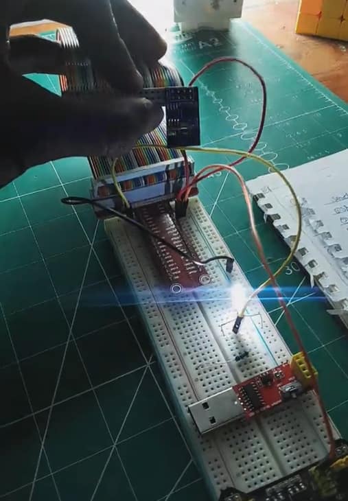
How to Program the ESP-01S Using the CH340 USB Adapter. Hey guys, it's been a while, hehe 🙂 . But I'll make it up to you with some news....
I just made a strategic partnership with Bluepack Nova, where we’ll hopefully have fun tutorial sessions from here on out. If you’ve been following my projects, you know I love diving deep into embedded systems, IoT, and automation. Today, we’re talking about one of the most popular Wi-Fi modules for DIYers—the ESP-01S—and how to program it using a CH340 USB adapter.
If you’ve ever struggled with flashing firmware or getting the ESP-01S to work properly, this guide is for you. I’ll walk you through the entire process, from setting up your hardware to troubleshooting common errors. Plus, I’ll sprinkle in some insider tips that will save you a ton of frustration.
Let’s get started.
Table Of Contents
The Circuit

What You’ll Need - ESP-01S WiFi module - CH340 USB to ESP-01 adapter - Arduino IDE
The Hardware
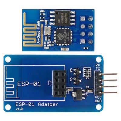
The ESP-01S WiFi module
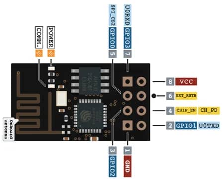
The ESP
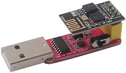
ACH340 USB to ESP-01 adapter
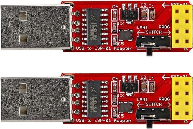
The Programmer
A Jumper Cables

The Jumper Cables
Push button (optional)

Push Button
To add a reset button for easy rebooting after flashing (I’ll show you how!)
External LED
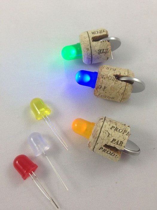
The LEDs
This will be blinked by the ESP-01
220 ohm Resistor

Resistors
To turn On the LED
(ESP8266 or Raspberry Pi GPIO Expander)GPIO Extender
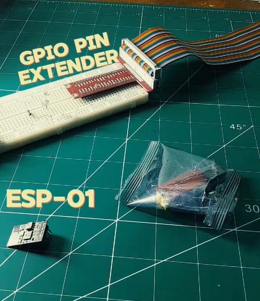
To expose GPIO2 on a breadboard for easier external connections. You could also solder your own using female headers.
The Software
ArduinoIDE

(or ESPTool, NodeMCU Flasher). This is a text editor that we ill use to program out microcontroller. If you’re familiar with VS code (Not vs code studio, if you use this bruh, I am not familiar with your game….eyyy mad respect).
(Download Here)
CH340 -driver
(Download here)
ESP8266 Board Package
(Install via Arduino Board Manager)
Step-by-Step Guide
Step 1:Setting Up the CH340 USB Adapter
Insert the ESP-01S module into the CH340 adapter.
Connect the adapter to your computer using via the USB port.
If your CH340 adapter has a programming switch, set it to Flash mode before proceeding.
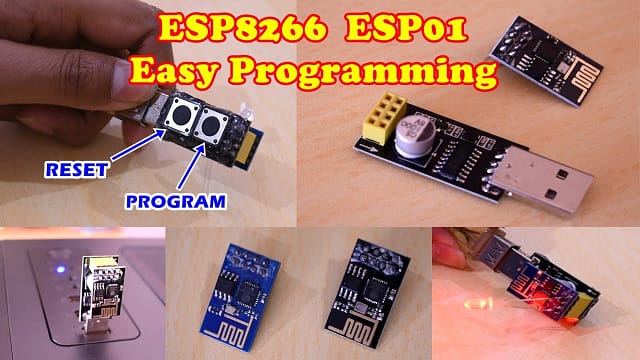
Insider Tip: If your CH340 adapter doesn’t have a reset button, you’ll need to unplug and replug the module after flashing. To avoid this hassle, you can solder a small push button between RST and GND—a simple mod that saves time!

Step 2:Installing CH340 Drivers
The CH340 USB-to-serial chip needs drivers for your computer to recognize it.
Windows: Download and install the CH340 driver, then restart your PC.
Mac: Use the Mac-compatible driver from the same link.
Linux: Run
sudo apt install ch341in the terminal.
To check if the driver is installed:
Open Device Manager (Windows) or ls /dev/ttyUSB0 (Linux/Mac).
If you see CH340 listed, you’re good to go.
Step 3:Configuring the Arduino IDE
Open Arduino IDE and go to File > Preferences.
In Additional Board Manager URLs, add:
http://arduino.esp8266.com/stable/package_esp8266com_index.jsonGo to Tools > Board > Board Manager, search for ESP8266, and install it.
Select Generic ESP8266 Module as your board.
Set Upload Speed to 115200 baud for better reliability.
Step 4:Writing & Uploading Code
Example Code: Blinking an LED
void setup() {
  pinMode(2, OUTPUT); // Built-in LED on ESP-01S
}

void loop() {
  digitalWrite(2, HIGH);
  delay(1000);
  digitalWrite(2, LOW);
  delay(1000);
}
Adding an External LED via GPIO Extender
To expose GPIO2 for an external LED, use a GPIO extender (ESP8266 GPIO Expander or Raspberry Pi GPIO Extender) to place the ESP-01S onto a breadboard. Then, connect the external LED to GPIO2 through a 220-ohm resistor.

This Exposes the ESP-01S pins that will allow us to blink the LED and if you’re thinking what I’m thinking you can pretty much toggle anything like a relay. This can allow you to create amazing IOT projects with just this tiny versatile chip.
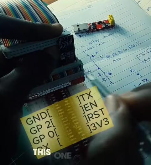
Why Do the LEDs Blink Alternately?
On the ESP-01S, GPIO2 is internally connected to an LED, which means that when GPIO2 is HIGH, the built-in LED turns OFF. When GPIO2 is LOW, the built-in LED turns ON. If an external LED is connected to GPIO2 through a GPIO extender, it will behave in reverse—turning ON when the internal LED turns OFF and vice versa.
But you probably don’t have a Raspberry Pi GPIO extender lying around so it’s perhaps best to swoop up those soldering skills and make your on like the one done below.

Flashing the Code
Press and hold the GPIO0 button (if your adapter has one) while connecting the USB.
Click Upload in Arduino IDE.
Once uploaded, restart the ESP-01S by unplugging and replugging it—or use the reset button mod!
Conclusion
Now that you’ve successfully programmed your ESP-01S, you’re ready to build exciting IoT projects. From Wi-Fi-controlled devices to sensor automation, the ESP-01S is a powerful tool in any maker’s arsenal.
Stay tuned for more tutorials, and don’t forget to check out Bluepack Nova for all your IoT hardware needs.
What’s Next?
Flashing custom firmware like MicroPython
Using AT commands to communicate with the ESP8266
Connecting your ESP-01S to the cloud for IoT applications
Got questions? Drop them in the comments below! Let’s build something awesome together.
