Heres What You’ll Learn.
1. Introduction
2. Components and Setup
2.1 MPU6050
2.2 Arduino
2.3 Servo Motor
3. MPU6050_light Library
3.1 Introduction to the MPU6050_light Library Functions.
3.2 Installation4. Arduino Code
4.1 Coding Explanations.
4.2 Testing and Calibration5. Enhancements and Projects
6. Dealing with Drift in MPU6050 Motion Control Systems
Introduction
Welcome to the world of motion control, where precision meets innovation! In this tutorial, we’ll delve into the exciting realm of combining the MPU6050 accelerometer and gyroscope sensor with a servo motor to create a dynamic and responsive motion system.
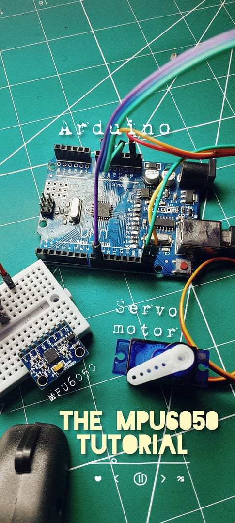
Components and Setup
MPU6050 Sensor
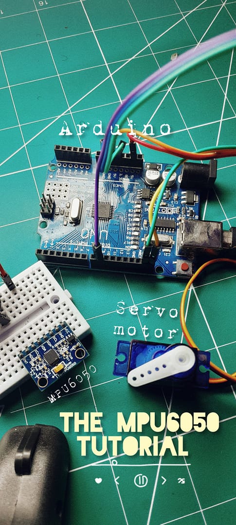
In this section, we’ll guide you through the process of selecting and setting up the MPU6050 sensor, as well as connecting it to the Arduino. The MPU6050 serves as our eyes and ears, equipped with an accelerometer and gyroscope to capture the nuances of movement. This versatile sensor is a staple in robotics, and today, we’ll harness its capabilities to drive the motion of a servo motor.
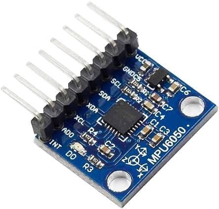
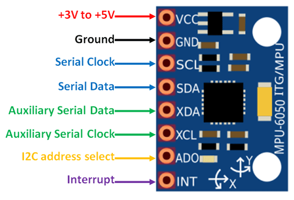
Setup of MPU6050 Sensor
- Power Supply:
– Connect the VCC (Voltage Common Collector) pin of the MPU6050 to the power source, adhering to the sensor’s voltage specifications.
- Ground Connection:
– Establish a common ground reference by connecting the GND (Ground) pin of the MPU6050 to the ground (GND) on the Arduino.
- Data Communication:
– For bidirectional data communication, connect the SDA (Serial Data Line) pin of the MPU6050 to the corresponding SDA pin on the Arduino.
- Clock Synchronization:
– Ensure proper timing for data exchange by connecting the SCL (Serial Clock Line) pin of the MPU6050 to the SCL pin on the Arduino.
Arduino Microcontroller
An Arduino microcontroller is a compact, programmable device developed by the Arduino company, widely embraced in the maker community, education, and DIY projects. Designed for user-friendliness, it enables individuals of all technical levels to easily create and experiment with electronics.

Connecting the Servo Motor to Arduino
To establish the connection between the servo motor and Arduino, follow these steps:
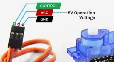
- Power Supply:
– Connect the power wire (usually red) of the servo motor to the 5V output on the Arduino. Ensure that you adhere to the voltage requirements of your servo motor.
- Ground Connection:
– Create a common ground reference by connecting the ground wire (usually brown) of the servo motor to any ground (GND) pin on the Arduino.
- Control Signal:
– Connect the control wire (usually orange or yellow) of the servo motor to a digital PWM (Pulse Width Modulation) pin on the Arduino. This pin will be used to send control signals to the servo motor.

By establishing these connections, you enable the Arduino to send signals to the servo motor, controlling its position based on the data received from the MPU6050 sensor. This collaboration between Arduino, MPU6050, and the servo motor forms the core of our motion control project.
Servo Motor
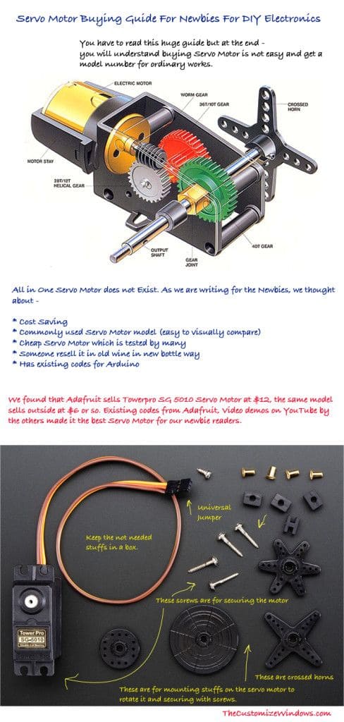
In this section, we’ll delve into the role of the servo motor in our project, emphasizing its response to MPU6050 data. Additionally, we’ll explore various options for selecting a suitable servo motor for your specific project requirements.
Role of the Servo Motor
The servo motor plays a crucial role in translating the orientation data obtained from the MPU6050 sensor into physical motion. As the MPU6050 detects changes in tilt or rotation, the servo motor adjusts its position accordingly. This capability makes servo motors ideal for applications that require precise and controlled movement.
Options for Selecting a Servo Motor
When choosing a servo motor for your project, consider the following factors:
- Torque Requirements:
– Evaluate the torque specifications of the servo motor to ensure it can handle the mechanical load and movement requirements of your project.

- Speed and Response Time:
– Different servo motors have varying speeds and response times. Choose a motor that aligns with the dynamic requirements of your application.
- Size and Form Factor:
– Consider the physical size and form factor of the servo motor, especially if space constraints are a consideration in your project.
- Voltage and Compatibility:
– Ensure that the servo motor operates within the voltage range supported by your project. Additionally, check for compatibility with the Arduino and MPU6050.
- Feedback Mechanism
– Some servo motors come with feedback mechanisms, such as positional sensors. These features can enhance precision and control in motion applications.

MPU6050_light Library
Introduction to the MPU6050_light Library
The MPU6050_light library is a valuable tool designed to streamline the process of interfacing with the MPU6050 sensor. By offering a convenient abstraction layer, this library simplifies integration and interaction with the MPU6050, making it an ideal choice for developers seeking an efficient and user-friendly solution.
Advantages of Using the Library
– Simplified Interfacing: With the MPU6050_light library, developers can bypass the complexities associated with direct manipulation of MPU6050 registers. This simplification is particularly beneficial for those new to sensor interfacing.
– Improved Readability: The library enhances code readability by encapsulating intricate procedures. Developers can focus on utilizing MPU6050 data without getting bogged down by low-level details.
– Efficient Data Handling: Designed for optimal performance, the library ensures streamlined and accurate retrieval of sensor readings. This efficiency contributes to the overall responsiveness and effectiveness of your project.
MPU6050_light library, a pivotal tool designed to seamlessly integrate the MPU6050 sensor into the programming fold.
In Case You don’t have the Arduino IDE You can get the software via the official Arduino website through the link Below.
The MPU6050_light library simplifies interfacing with the MPU6050 sensor by providing a set of functions and features that facilitate easy integration into Arduino projects. Here’s an overview of some key functions incorporated in the MPU6050_light library:
MPU6050_light Library Functions
- `mpu.begin()`: This function initializes communication with the MPU6050 sensor. It establishes a connection and performs necessary setup procedures.
- `mpu.update()`: Periodically calling this function updates sensor data. It reads new accelerometer and gyroscope values, allowing real-time access to motion-related information.
- `mpu.getRawAccX()`, `mpu.getRawAccY()`, `mpu.getRawAccZ()`: These functions provide raw accelerometer data along the X, Y, and Z axes, respectively.
- `mpu.getRawGyroX()`, `mpu.getRawGyroY()`, `mpu.getRawGyroZ()`: Similarly, these functions offer raw gyroscope data along the X, Y, and Z axes.
-`mpu.getAccX()`, `mpu.getAccY()`, `mpu.getAccZ()`: These functions return scaled accelerometer values, taking into account the sensor's sensitivity settings.
- `mpu.getGyroX()`, `mpu.getGyroY()`, `mpu.getGyroZ()`: Similarly, these functions provide scaled gyroscope values.
- `mpu.getAngleX()`, `mpu.getAngleY()`, `mpu.getAngleZ()`: These functions calculate and return the roll, pitch, and yaw angles, respectively, based on the sensor data.
- `mpu.setAccOffsets(int offsetX, int offsetY, int offsetZ)`: This function allows setting specific offsets for the accelerometer to correct for any bias.
- `mpu.setGyroOffsets(int offsetX, int offsetY, int offsetZ)`: Similarly, this function sets offsets for the gyroscope.
- `mpu.calcOffsets()`: This function calculates and sets offsets for both the accelerometer and gyroscope automatically. It's particularly useful during the initial setup phase.
- `mpu.setAccSensitivity(int sensitivity)`: This function sets the accelerometer sensitivity (±2g, ±4g, ±8g, or ±16g).
- `mpu.setGyroSensitivity(int sensitivity)`: Similarly, this function configures the gyroscope sensitivity (±250°/s, ±500°/s, ±1000°/s, or ±2000°/s).
- `mpu.setSampleRate Divider(int divider)`: This function adjusts the sample rate divider, influencing the update rate of sensor data.
- `mpu.setDLPFMode(int mode)`: This function sets the Digital Low-Pass Filter (DLPF) configuration, affecting the trade-off between noise and response time.
- `mpu.testConnection()`: This function checks whether the MPU6050 sensor is properly connected and responsive.
These functions encapsulate various functionalities of the MPU6050 sensor, allowing developers to easily access motion-related data and configure sensor settings in their Arduino projects.
Installation
Using Arduino IDE Library Manager (Ctrl+Shift+I)
- Open Arduino IDE:
– Launch the Arduino IDE on your computer.
- Access Library Manager:
– Navigate to “Sketch” > “Include Library” > “Manage Libraries…”
- Search for MPU6050_light:
– In the Library Manager, use the search bar to look for “MPU6050_light.”
- Install the Library:
– Once located, select the MPU6050_light library from the list.
– Click “Install” to initiate the installation process.
- Verify Installation:
– After installation, close and reopen the Arduino IDE to ensure proper recognition of the newly added library.
Note: I do acknowledge the presence of drift-related challenges in motion sensing applications. In subsequent sections, we will delve into an explanation of drift, its implications, and effective strategies to mitigate its impact on sensor readings. Stay tuned for a comprehensive understanding of this crucial aspect.
Arduino Code
::::The Code
/* Get tilt angles on X and Y, and rotation angle on Z
 * Angles are given in degrees
 *
 * License: MIT
 */

#include "Wire.h"
#include
#include

MPU6050 mpu(Wire);
Servo myservo;

const int servoPin = 9;
unsigned long timer = 0;
int a = 0;

void setup() {
  Serial.begin(9600);
  initializeServo();
  initializeMPU();
}

void loop() {
  mpu.update();

  if (shouldPrintData()) {
    printAngles();
    timer = millis();
  }

  controlServo();
}

void initializeServo() {
  myservo.attach(servoPin);
}

void initializeMPU() {
  Wire.begin();
  byte status = mpu.begin();
  Serial.print(F("MPU6050 status: "));
  Serial.println(status);

  while (status != 0) { } // Stop if could not connect to MPU6050

  Serial.println(F("Calculating offsets, do not move MPU6050"));
  delay(1000);
  // mpu.upsideDownMounting = true; // Uncomment this line if the MPU6050 is mounted upside-down
  mpu.calcOffsets(); // Gyro and accelerometer
  Serial.println("Done!\n");
}

bool shouldPrintData() {
  return (millis() - timer) > 10; // Print data every 10ms
}

void printAngles() {
  Serial.print("X : ");
  Serial.print(mpu.getAngleX());
  Serial.print("\tY : ");
  Serial.print(mpu.getAngleY());
  Serial.print("\tZ : ");
  Serial.println(mpu.getAngleZ());
}

void controlServo() {
  a = mpu.getAngleZ();
  a = map(a, 0, 180, 0, 180); // Ensure 'a' is within servo limits
  myservo.write(a);
  delay(15);
}
Download Code Files Here.
Get access to all program files via this gitHUB Link. If you have any issues feel free to contact me.
Code Explanations
Reading MPU6050 Data
In this section, we will walk through the step-by-step explanation of the code responsible for initializing, reading data from the MPU6050, and extracting roll, pitch, and yaw angles and translating that the Servo Motor.
1: Include Libraries and Declare Objects
    Eyyyyyyy ;)
    ```cpp
#include "Wire.h"
#include
#include

MPU6050 mpu(Wire); // Create an instance of the MPU6050 class
Servo myservo;      // Create a servo object

const int servoPin = 9; // Define the servo signal pin
unsigned long timer = 0;
int a = 0; // Initialize the angle variable
```
– Wire.h: Library for I2C communication.
-MPU6050_light.h: Library for interfacing with the MPU6050 sensor.
– Servo.h: Library for servo motor control.
– mpu: Instance of the MPU6050 class to interact with the sensor.
– myservo: Servo object to control the servo motor.
– servoPin: Digital pin to which the servo is connected.
– timer: Keeps track of the time for printing data.
– a: Variable to store the angle.
2. Setup Function
```cpp
void setup() {
  Serial.begin(9600);  // Initialize serial communication
  initializeServo();    // Call function to initialize the servo
  initializeMPU();      // Call function to initialize the MPU6050
}
```
– Serial.begin(9600): Initializes serial communication at a baud rate of 9600.
– initializeServo(): Calls the function to initialize the servo.
– initializeMPU(): Calls the function to initialize the MPU6050 sensor.
3: Servo Initialization Function
```cpp
void initializeServo() {
  myservo.attach(servoPin); // Attach the servo to the specified pin
}
```
– myservo.attach(servoPin): Attaches the servo to the defined pin.
4. MPU6050 Initialization Function
```cpp
void initializeMPU() {
  Wire.begin();          // Begin I2C communication
  byte status = mpu.begin(); // Initialize the MPU6050 and get its status
  Serial.print(F("MPU6050 status: "));
  Serial.println(status);

  while (status != 0) { } // Stop if could not connect to MPU6050

  Serial.println(F("Calculating offsets, do not move MPU6050"));
  delay(1000);
  // mpu.upsideDownMounting = true; // Uncomment this line if the MPU6050 is mounted upside-down
  mpu.calcOffsets(); // Gyro and accelerometer
  Serial.println("Done!\n");
}
```
– Wire.begin(): Initializes I2C communication.
– mpu.begin(): Initializes the MPU6050 sensor and returns its status.
– mpu.upsideDownMounting: If uncommented, assumes the MPU6050 is mounted upside-down.
– mpu.calcOffsets(): Calculates offsets for gyro and accelerometer.
5. Loop Function
```cpp
void loop() {
  mpu.update();  // Update MPU6050 data

  if (shouldPrintData()) { // Check if it's time to print data
    printAngles(); // Call function to print X, Y, and Z angles
    timer = millis(); // Reset the timer
  }

  controlServo(); // Call function to control the servo
}
```
– mpu.update(): Continuously updates data from the MPU6050 sensor.
– shouldPrintData(): Checks if it’s time to print data based on a specified interval.
– printAngles(): Calls a function to print X, Y, and Z angles to the Serial Monitor.
– controlServo(): Calls a function to control the servo motor.
6. Condition for Printing Data
```cpp
bool shouldPrintData() {
  return (millis() - timer) > 10; // Print data every 10ms
}
```
– Returns `true` if it’s been more than 10 milliseconds since the last data print.
7. Printing Angles Function
```cpp
void printAngles() {
  Serial.print("X : ");
  Serial.print(mpu.getAngleX());
  Serial.print("\tY : ");
  Serial.print(mpu.getAngleY());
  Serial.print("\tZ : ");
  Serial.println(mpu.getAngleZ());
}
```
– Prints X, Y, and Z angles from the MPU6050 to the Serial Monitor.
8. Servo Control Function
```cpp
void controlServo() {
  a = mpu.getAngleZ();
  a = map(a, 0, 180, 0, 180); // Map 'a' to ensure it stays within servo limits
  myservo.write(a); // Set servo angle
  delay(15); // Delay for stability

  // Check and reset 'a' to prevent exceeding servo limits
  if (a > 180) {
    a = 0;
  }
}
```
– a = map(a, 0, 180, 0, 180): Maps ‘a’ to ensure it stays within servo limits (0 to 180).
– myservo.write(a): Sets the servo angle.
– delay(15): Introduces a delay for stability.
– Checks and resets ‘a’ to prevent exceeding servo limits.
These detailedThis step-by-step breakdown provides a clear understanding of the code for reading MPU6050 data and extracting orientation angles.
Testing and Calibration
During real-time testing, you will verify the functionality of the servo motor control with MPU6050. This involves observing the servo movement in response to different orientations detected by the MPU6050 sensor. Ensure that the servo accurately reflects changes in the sensor’s orientation, providing a visual representation of the motion-controlled system.
Calibration Tips
Calibration is crucial for optimizing the performance of the MPU6050 sensor and achieving precise control over the servo motor. Follow these tips for effective calibration:
- Minimize Drift:
– Implement strategies to minimize sensor drift, especially during prolonged operation.
- Sensor Placement:
– Ensure proper placement of the MPU6050 sensor to minimize external interferences.
- Fine-tune Parameters:
– Adjust sensor parameters to fine-tune its responsiveness and accuracy.
- Servo Mapping Adjustment:
– Fine-tune the mapping of MPU6050 angles to servo positions for precise control.
Enhancements and Projects
Adding More Servos
To enhance the project, consider expanding the system by controlling multiple servo motors simultaneously. Modify the code to accommodate and manage multiple servos effectively. This enhancement opens up possibilities for more complex and dynamic motion-controlled scenarios.
Gesture-Based Control
Take your project to the next level by incorporating gesture-based control using MPU6050 data. Implement specific gestures that, when detected by the sensor, trigger predefined movements of the servo motors. This feature adds interactivity to your project, making it more engaging and versatile.
Dealing with Drift in MPU6050 Motion Control Systems
Motion control systems, especially those relying on sensors like the MPU6050, may encounter a phenomenon known as “drift.” Drift refers to the gradual deviation or shift in sensor readings over time, even when the sensor is at rest. Addressing drift is crucial for maintaining the accuracy and reliability of your motion-controlled servo system. Here are some methods to deal with drift effectively:

- Calibration at Regular Intervals:
– Regularly recalibrate your MPU6050 sensor at defined intervals. This involves resetting reference points and correcting any bias that may have accumulated during operation.
- Temperature Compensation:
– Drift can be influenced by temperature changes. Implement temperature compensation techniques to account for environmental variations and maintain sensor accuracy.
- Sensor Fusion with Complementary Filters:
– Integrate sensor fusion algorithms, such as complementary filters, to combine data from multiple sensors (e.g., gyro and accelerometer). This fusion helps mitigate drift issues by leveraging the strengths of different sensors.
- Use of External Reference Points:
– Incorporate external reference points, such as known positions or markers, to periodically reset the sensor. This approach can be especially useful in applications where the sensor returns to a known state.
- Gyroscope-Only Drift Correction:
– Utilize the gyroscope data specifically for drift correction. Gyroscopes provide angular rate information and can be used to compensate for drift, particularly in applications where angular velocity is a critical parameter.
- Advanced Calibration Techniques:
– Explore advanced calibration techniques beyond simple offset adjustments. Some sensors provide advanced calibration options, and fine-tuning these parameters can significantly reduce drift.
- Continuous Monitoring and Adaptation:
– Implement a system for continuous monitoring of sensor performance. If drift is detected, adapt the calibration parameters dynamically to counteract the effects of drift during operation.
- Data Filtering and Smoothing:
– Apply filtering and smoothing algorithms to the sensor data to reduce noise and fluctuations. This can enhance the signal-to-noise ratio and improve the sensor’s overall stability.
- Machine Learning-Based Drift Prediction:
– For advanced applications, consider employing machine learning algorithms to predict and compensate for drift patterns based on historical data. This adaptive approach can enhance long-term performance.
- Community and Expert Input:
– Engage with the maker and robotics communities to gather insights and best practices for drift mitigation. Forums, blogs, and discussions can provide valuable input from those who have tackled similar challenges.
Addressing drift in MPU6050-based motion control systems is an ongoing process that may require a combination of these methods. Experimentation, continuous monitoring, and adaptation are key aspects of maintaining optimal system performance over time. By actively managing drift, you ensure that your motion-controlled servo system remains accurate and reliable throughout its operational life.
I’d like to find out more? I’d like to find out more details. https://www.waste-ndc.pro/community/profile/tressa79906983/
Thankjs , I have just been looking for info about thi topi
for ags and yours is the best I’ve found out so far.
However, what about thee bottom line? Are you sure about the
source? https://Www.Waste-Ndc.pro/community/profile/tressa79906983/
Spot on with this write-up, I honestly feel
this amazing site needs much more attention. I’ll probably be back again to see more, thanks for the information! https://kesq.com/stacker-money/2022/12/15/youngest-billionaires-in-america/
Awesome article. https://wakelet.com/wake/1gtLmO-Q3iiPK9lVFnycx
I have read so many articles on the topic of the blogger lovers
except this post is in fact a nice paragraph, keep it up. https://caramellaapp.com/milanmu1/_zJdh2nHV/artemis-prostate-fusion-biopsy
Hi there, the whole thing is going well here and ofcourse
every one is sharing information, that’s genuinely good, keep up writing. https://urs-wiscope.mystrikingly.com/
Attractive section of content. I just stumbled upon your site and in accession capital to assert that I acquire
in fact enjoyed account your blog posts. Anyway I will
be subscribing to your feeds and even I achievement you access consistently rapidly. https://ire-electroporation.blogspot.com/2025/02/minimally-invasive-prostate-cancer.html
I got this website from my friend who told me on the
topic of this website and now this time I am visiting
this site and reading very informative content at this place. https://www.wtvm.com/2024/03/30/crimson-tide-clemson-tigers-set-battle-spot-final-four/
I don’t even know how I ended up here, but I thought this
post was good. I don’t know who you are but certainly you are going to a famous blogger
if you aren’t already 😉 Cheers!