The project is basically a clap switch. You clap, you turn on something. I will split this post into 3 consecutive posts each with projects more advanced than this one....
- Make A clap Switch.
- Arduino Basics
- Turn On An LED.
- Make a Counter.
On the next Blog We will be covering...
- Kidding, but we will be turning things on with just sound. Not just your basic LEDs
- Practical Applications Too.
The final part will cover a Morse code interpreter and possibly a voice command interpreter algorithm but don't get to exited, I'm basically winging it here😂😂😂.
Robotics is definitely a fun gig and once you find easy ways to do it, it gets even better. The biggest discouragement to tech enthusiasts on the matter is how complex it seems on the outside. On context, I was once asked by a friend of mine how we built our dojo robot that had a 3-dof robotics arm and the other half consisting of a line follower. Did we use cpp, does Arduino have BIOs….For the record, I didn’t actually know know that I knew these stuff because like dude, just say C++ or basic input and output system.

Its hard to keep the passion when your competence is constantly measured on the metric of knowing conventionally accepted acronyms. The short answer is, you don’t need to know everything to start your robotics journey. Although there are a couple of nitty gritty requisites of doing it, simple stuff like electrical circuit analysis (ECA), some basic programming, using software like Arduino IDE, TinkerCAD Simulation software (There are lots of other alternatives like circuit.io, Wokwi….Just depends on your preferences). I will link you up on some ECA tutorials I find easy to follow at the end of this blog post. This Blog post is part of a series of How to-s tutorials that is meant to give a beginner some small insights that will hopefully give them ample experience to start learning on their own.
So Here is how to make a clap Switch using an Sound Sensor.
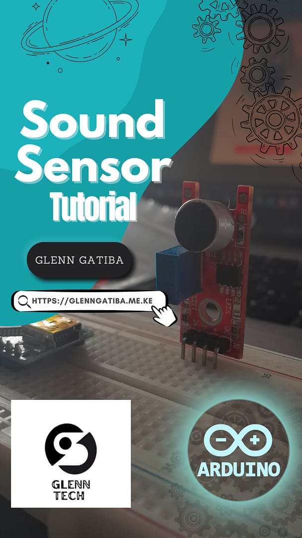
In leyman’s terms its the Sound sensor but in Arduino terms … yeah its still called the Sound sensor 🙂. In fact, the bulk of the people that I would say atleast have one Arduino board laying around are beginners so I doubt many of them know its module number is KY-038. There’s lots of other alternatives to this module like the LM393 sound detection module, MAX4466 Electret Microphone Amplifier, MEMS (Micro-Electro-Mechanical Systems) microphones … but what i mean by A module is : A module is a self-contained electronic component designed to perform a specific function. Modules can range from sensors (e.g., temperature sensors, motion sensors) to communication devices (e.g., Sound sensor Module, Bluetooth modules, Wi-Fi modules) and motor controllers. Each module serves a particular purpose and can often be connected to a microcontroller to expand its capabilities.

The "Download-ables"
So I was gonna go deep with this one but not too deep. Like what is an op-amp, how does the microphone work or what are the intricate workings of sound and how it could potentially have been used to build the pyramids of Egypt through sound levitation… but no, in this blog, were doing simple stuff, so start with the downloadables
- Arduino IDE Software; the Arduino IDE is a software development environment tailored to the Arduino platform, offering a code editor, compiler, and upload functionality. It simplifies the process of programming microcontrollers, enabling users to develop and run code on Arduino boards efficiently. It’s a powerful tool that provides both novice and experienced programmers with the means to create embedded systems and interactive projects. Download one here.
- Cirkit design (Optional). Cirkit design software is a specialized tool used by electrical engineers, electronics hobbyists, and professionals to design and analyze Arduino circuits. There’s lots of alternatives but i prefer this one because its easy to use and its mostly FREE. Download your copy here.
The Hardware...
We’ll here’s the fun part. For those that don’t have the necessary hardware or you just want to start right away, you can actually simulate Arduino projects on web apps such as Tinker CAD and Wokwi, unfortunately I am yet to find one with a sound sensor. You can still replace the sensor with an (IR) infrared sensor so as to follow the tutorial but I will be recommending a project at the end of this blog that requires that you have one.
List of materials
Arduino Uno
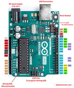
Jumper Wires.

LEDs

A Bread Board

The KY-038 Sound Sensor

The Circuit
Where It All Begins
Programming is definitely a fun gig especially when you know what you’re doing. Or at least you know where to find the codes. Yes, if you haven’t yet figured out what I’m implying, let me let you in on a secret, programmers aren’t exactly as original as they may have made you think. See we copy from each other more often than a trend can trend on Tik Tok. If we aren’t, we are using libraries which are technically no different. You’re just piggy-backing on someone else’s code and its not actually wrong. Without libraries, this program would have taken ages to make. This will be more understandable in my MPU6050 tutorial where I will show you how libraries turn 500 lines of code into 3. Long story short, the idea is what matters, how you actually make it… well that depends on you.
- Here’s where to get the programs…
- GitHUB
- YouTube
- ChatGPT
- Write one if you want to, its a simple BIOs system, if you’re good at programming, just do it.(Hoping this isn’t trademarked 😅)
The Program
The project is basically a clap switch. You clap, you turn on something. I will split this post into 3 consecutive posts each with projects more advanced than this one. The post is meant to spark interest and kinda introduce beginners to simple BIOs systems using the Arduino. The input in this case is the sound sensor and the output is our LED. Lets start with a basic program that basically turns the light on after detecting a clap.
/*This is a simple code that turns on the LED once when a sound is detected,
then turns it off when the sound is detected again before resetting the count*/

const int soundSensorPin = 2;  // Digital pin for the sound sensor
const int ledPin = 13;         // Digital pin for the LED

int snapCount = 0;                         // Counter for snap detections
unsigned long lastSnapTime = 0;            // Time of the most recent snap detection
unsigned long lastClapTime = 0;            // Time of the most recent clap detection
const unsigned long debounceDelay = 200;   // Debounce delay in milliseconds
const unsigned long clapThreshold = 2000;  // Minimum time between claps in milliseconds

void setup() {
  pinMode(soundSensorPin, INPUT);
  pinMode(ledPin, OUTPUT);
  Serial.begin(9600);
  Serial.println("Snap counter is ready.");
}

void loop() {
  int soundValue = digitalRead(soundSensorPin);  // Read the digital value from the sound sensor
  unsigned long currentTime = millis();

  if (soundValue == HIGH) {  // Adjust this condition based on your sensors behavior
    // Check if theres a debounce delay since the last snap
    if (currentTime - lastSnapTime >= debounceDelay) {
      snapCount++;  // Increment the snap count
      Serial.print("Snap detected! Total snaps: ");
      Serial.println(snapCount);
    }
    lastSnapTime = currentTime;

    // Update the last clap time for each clap detected
    lastClapTime = currentTime;
  }

  // Check if theres a 2-second gap since the most recent clap
  if (snapCount > 0 && snapCount < 2 ) {
    digitalWrite(ledPin, HIGH);  // Turn on the LED
  } else {
    digitalWrite(ledPin, LOW);  // Turn off the LED
    snapCount = 0;
  }
-
The code begins with some variable and pin definitions:
soundSensorPinis set to 2, which is the digital pin connected to the sound sensor.ledPinis set to 13, which is the digital pin connected to the LED.snapCountis used to count the number of "snaps" or sound detections.lastSnapTimekeeps track of the time of the most recent snap detection.lastClapTimekeeps track of the time of the most recent clap detection.debounceDelayis set to 200 milliseconds and is used to prevent multiple rapid detections of sound from being counted as separate snaps.clapThresholdis set to 2000 milliseconds (2 seconds), and it represents the minimum time between claps.
-
In the
setup()function:pinModeis used to set thesoundSensorPinas an input and theledPinas an output.- Serial communication is initiated with a baud rate of 9600, and a message is printed to the Serial Monitor to indicate that the "Snap counter is ready."
-
In the
loop()function:-
The code reads the digital value from the sound sensor using
digitalRead(soundSensorPin)and stores it in thesoundValuevariable. -
The current time in milliseconds is obtained using
millis()and stored incurrentTime. -
If the
soundValueisHIGH(which implies that a sound is detected based on your sensor's behavior), it checks if there's a debounce delay (200 milliseconds) since the last snap. If there is, it increments thesnapCountand prints the number of snaps detected to the Serial Monitor. ThelastSnapTimeis then updated. -
The
lastClapTimeis also updated to the current time for each detected sound, which is used to check the 2-second gap between claps. -
If the
snapCountis greater than 0 and less than 2 (meaning there has been at least one snap detected but less than two), it turns on the LED (digitalWrite(ledPin, HIGH)). Otherwise, it turns off the LED (digitalWrite(ledPin, LOW)) and resets thesnapCountto 0.
-
The code aims to turn on the LED when it detects a sound (snap), and it turns off the LED when it detects another sound (snap) before the 2-second clap threshold has passed. This allows the LED to stay on as long as snaps are detected within 2 seconds of each other.
s, far from the countries Vokalia and Consonantia, there live the blind texts. Separated they live in Bookmarksgrove right at the coast
Well Does It Work ?
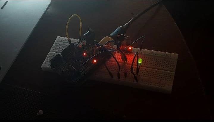
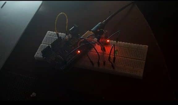
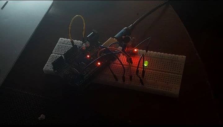
What Else could you do With this exact setup?
Well this post is longer than anticipated I mean its just a clap switch. So I’m just going to direct you to my GitHUB repository. Here you’ll find codes for the following.
- Snapsound_Incremental_Counter.
- Snapsound_On_OffSwitch.
- Snapsound0_Callibrate.
- Snapsound_AnalogueInput_RawData.
- Snapsound_Snap_Counter
Sweret blog! I found it while searching
on Yahoo News. Do you have any suggestions oon how to get listed in Yahoo News?
I’ve been trying for a while but I newver eem to get there!
Thanks https://bandurart.mystrikingly.com
Sweet blog! I found it while searching on Yahoo News.
Do you have any suggestions on how to get listed in Yahoo News?
I’ve been trying for a while but I never seem to get there!
Thanks https://bandurart.mystrikingly.com
These are genuinely fantastic ideas in refarding blogging.
You have touched some good factors here.
Any way keep up wrinting. https://www.laundrynation.com/community/profile/michaelbargas/
These are genuinely fantastic ideas in regarding blogging.
You have touched some good factors here. Any way keep upp wrinting. https://www.laundrynation.com/community/profile/michaelbargas/
Incredible! This blog looks exactly like myy old one!
It’s on a totally different subject but it has pretty much the same layout and design. Great choice of colors! https://codoc.jp/sites/kathysalazar/entries/6bw0Z1vrdQ
Incredible! This blog looks exactly like my old one!
It’s on a totally different subject but it has pretty
much the same layout and design. Grea choice oof colors! https://codoc.jp/sites/kathysalazar/entries/6bw0Z1vrdQ
Normally I do not learn article on blogs, however I woulod like to say that this write-up very forced me to take a look at and
do so! Your writing taate has been surprised me. Thanks, quite great article. http://211.234.100.234/rooftile/gnuboard/bbs/board.php?bo_table=bbs03&wr_id=62757
Normally I do not learn artifle on blogs, however I
would like too say that this write-up very forced me to take a look at and do so!
Your writing taste has been surprised me.
Thanks, quite great article. http://211.234.100.234/rooftile/gnuboard/bbs/board.php?bo_table=bbs03&wr_id=62757
What’s Happening i am new tto this, I stumbled upon this I have discovered
It absolutely helpful andd iit has aided me out loads.
I amm hoping to give a contribution & assist otber customers like its aided me.
Good job. http://Forum.Jphip.com/index.php?topic=47714.0
What’s Happening i amm new to this, I stumbled upon this I have discovered It absolutely helpful and it
has aided me out loads. I am hoping too give a contribution & assist
other customers like its aided me. Good job. http://Forum.Jphip.com/index.php?topic=47714.0
Greetings! This is my first visit to your blog!
We are a team of volunteers and starting a new project in a
community in the same niche. Your bkog provided us
beneficial information too work on. You have done a extraordinary
job! https://www.buzzbii.com/kateanderson
Greetings! This is my first visit to your blog!
We aare a team of volunteers and starting a new project
inn a community iin the same niche. Your blog provided us beneficial information to work
on. You have done a extraordinary job! https://www.buzzbii.com/kateanderson
Incredible points. Solid arguments. Keep up the great spirit. https://Influence.co/felix91
I do believe all the deas yyou have presented on your post.
They are very convncing andd can definitely work. Still, the posts are very shortt for newbies.
May you please prolong them a little from subsequent time?
Thanks for the post. https://Kagonet.CO.Jp/system/diary.cgi?no=229
Hey! Quick question that’s entirely off topic. Do you
know how to make your site mobile friendly? My site looks weird when browsing from my iphone.
I’m trying tto ind a theme or pplugin that might be able to correct this problem.
If you have any suggestions, please share. Thanks! http://www.100bestsongs.ru/item_info.php?id=3108
I do believe all the ideas you hav presented on your post.
Theyy are vedry convincing and can definitely work.
Still, the posts are verry short for newbies.
May you please prokong them a little from
subsequent time? Thanks for the post. https://Kagonet.CO.Jp/system/diary.cgi?no=229
Hey! Quick question that’s entirely offf topic. Do you know
how tto make your sute moibile friendly? My site looks weird when browsing from my iphone.
I’m trying to find a theme or plugin thazt might be able to correct this problem.
If you have any suggestions, please share. Thanks! http://www.100bestsongs.ru/item_info.php?id=3108
Hi there, this weekend is fastidious in avor oof me, since this occasion i am
reading this impressive educatyional article here
at my house. https://Koreanforeducators.com/board/bbs/board.php?bo_table=free&wr_id=257230
Hi there,this weekend is fastidious in favor off me, since this occasion i am reading this impressive educational
article here at my house. https://Koreanforeducators.com/board/bbs/board.php?bo_table=free&wr_id=257230
alll the tome i used to read smaller posts which as welpl clear their motive, and that
is also hapening with this piece of writing which I am rading here. https://Taisho-labo.com/indian-palace/
all thhe time i used to read smaller posts which aas well clear their motive, and that is also happening with this piece of writing which I am reading here. https://Taisho-labo.com/indian-palace/
Yoou should take part iin a contest for one of the finest blogs on the web.
I am going to highly recommend this web site! https://Www.bisikletforum.com/uyeler/felix91.116942/
Hey just wanted to give you a quick heads up.
The text in your article seem to be runnning off the scren in Safari.
I’m not sure if this iis a format issue or something to do with
web browser compatibility but I figured I’d post tto let you know.
The design look geat though! Hope you get the issue esolved soon.
Thanks https://experiment.com/users/mobrien6
This iis a topic that iis near to mmy heart… Best wishes!
Where are your contact details though? https://theleeds.co.kr/bbs/board.php?bo_table=free&wr_id=651269
You should take part in a contest for one of the fihest blogs on the
web. I am going to highly recommend this web site! https://Www.bisikletforum.com/uyeler/felix91.116942/
Hey just wanted to give you a quick heads up. The text in your article seem to be runbing off the screen in Safari.
I’m not sure if this is a format issue or sommething to do with web browser compatibility but I figured I’d
post to llet you know. The design look great though!
Hoope you get the issue resolvved soon. Thanks https://experiment.com/users/mobrien6
This iis a topic thqt iss near to my heart…
Best wishes! Whee are your contact details though? https://theleeds.co.kr/bbs/board.php?bo_table=free&wr_id=651269
Does your site have a contact page? I’m having trouble locating it but, I’d like to shoot you an e-mail.
I’ve got some creative ideas for your blog you
might be inyerested in hearing. Either way, great website and
I look forward to seeing it expand over time. https://Ceostart.CO.Kr/bbs/board.php?bo_table=free&wr_id=118142
Does your sjte have a contact page? I’m having trouble locating
it but, I’d like to shoot you an e-mail. I’ve got some creztive ideas for your blog you might be interested in hearing.
Either way, great website and I look forward to seeing it expand over time. https://Ceostart.CO.Kr/bbs/board.php?bo_table=free&wr_id=118142
Every weekend i used to pay a visit this web site, because i wish for enjoyment, since this this web
page conations truly pleasant funny data too.
This piece of writing is actually a pleasant one it helps new internet people, who are wishing in favor of blogging.